Description
The pulse emitter reed switches operate as potential-free, dry-contact systems. They are specifically tailored for integration into automated systems, such as matching with a Seko dosing pump or telemetry logger.
Key Specifications & Configurations
- Maximum Switching Voltage: 24V AC/DC
- Maximum Switched Current: 0.01A (10 mA)
- Standard Cable Length: 1.5 meters
- Operational Temperature Limits: Certified safe for water mediums up to 50°C (T50 model rating).
Wiring Options
- 2-Core Configuration: Consists of a Red and Black wire housing a single reed switch.
- 3-Core Configuration: Consists of a Red, Black, and Blue wire housing 2 reed switches. This setup provides a secondary offset contact to verify flow direction or filter out structural line vibrations.
Physical Design & Protection
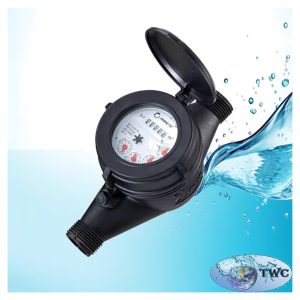
- Housing: The assembly features an external plastic casing designed to fit directly into the pre-molded mounting slot on the meter’s index head.
- Magnetic Protection: Built-in insulation ensures that external magnetic fields or tampering attempts cannot manipulate the rotation register or falsely trigger the reed pulse contacts.
- Standard K-Factor (Pulse Weight): Typically aligned to register 10 Liters per pulse (corresponding to the x0.001 position dial on the Multi-Jet mechanical register).
When you connect a reed switch to an external system, you are converting physical water volume into a digital signal. Because a reed switch is a potential-free, dry contact (essentially a mechanical switch that snaps shut when a magnet passes), it does not output voltage on its own. Instead, the receiving device must supply a small sensing voltage to detect when the circuit closes.
1. Connecting to an External PLC (Programmable Logic Controller)
PLCs are used in industrial automation, factory systems, or municipal water treatment plants. To monitor flow rates and control heavy machinery like valves.
- How it Works: The PLC supplies a constant “sensing voltage” (usually 24V DC) down one wire. When the water meter’s magnet closes the reed switch, the voltage flows back to a Digital Input (DI) card on the PLC, registering a pulse.
2. Connecting to a Battery-Powered Data Logger
Data loggers are used for remote monitoring, telemetry, smart metering, and water conservation tracking in areas without mains electrical power.
- How it Works: The data logger stays in a low-power “sleep mode” to save its battery. When the water meter’s reed switch closes, it triggers a hardware wake-up interrupt on the logger. The logger wakes up, increments the pulse count in its internal memory by 1, and immediately goes back to sleep.
- Key Consideration (Current Draw): The switch is rated for a maximum of 10 mA. Data loggers naturally use micro-amps making them perfectly safe. However, ensure the logger is configured for a pull-up resistor setup that matches this low-current threshold so it does not burn out the tiny internal contacts of the reed switch over time.
3. Connecting to a Chemical Dosing Pump
This setup is highly common in agricultural irrigation, water purification, and chlorination systems (often utilizing Seko dosing pumps).
- How it Works (Proportional Dosing): You program the dosing pump to inject a precise micro-dose of chemical (like chlorine, fertilizer, or acid) relative to the volume of water passing through the pipe.
- The Calculation: Because the meter typically sends 1 pulse every 10 Liters, you program the pump’s interface to understand that 1 pulse incoming on its control cable equals exactly 10 Liters of flow. If your recipe requires 2 mL of chemical per Liter of water, you program the pump to stroke or inject exactly 20 mL of chemical every time it receives a pulse.
Reed Switches